Fuel assessments, Biomass combustion and handling support
Microscopy
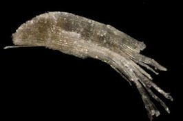
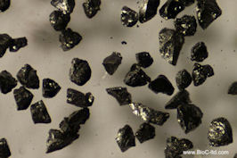
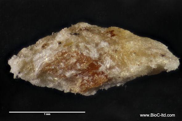
BioC can offer Microscopy and image analysis of fuel particles. Our speciality is biofuels and assessment of particle shape, which is essential for accurate computer simulation of biomass combustion. The pictures below show some fuel particles photographed through a light microscope. The very narrow depth of focus in a microscope is overcome by taking a number of pictures with a slight shift in focus between them (typically 20-30 pictures for a 1 mm particle) and then letting a computer combine them into one picture that is sharp all the way through.
The importance of the particle shape for the combustion
The shape of a fuel particle affects both its aerodynamic behaviour and combustion. A particle with larger surface area
will burn faster than a spherical one as the heat absorption by the particle surface, diffusion of gases to and from the
surface and the chemical reactions taking place at the surface all contribute to a faster process. The diagram below
shows the result of a simulation of the drying and devolatilisation of a 1mm biomass particle with 10% moisture and 85%
volatile matter. This simulation has been made using a BioC proprietary model but is consistent with published data
[one example is: Yang Y B et. al., Energy & Fuels, 2008, 22, 306-316].
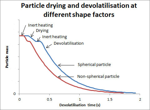
The diagram shows how the particle mass changes with time for an initially 1 mm particle that goes through heating, drying, further heating and finally devolatilisation, char combustion is not modelled here. The blue line symbolises a spherical particle and the red line is a non-spherical particle with twice the surface area of the spherical particle. Both particles start with the same mass, and all other parameters are identical, it is only the shape that differs. The heating and drying stages take approximately twice as long for the spherical particle, which will be an important factor for flame stability. Burnout is significantly faster for the non-spherical particle which will affect the amount of carbon in the fly ash. At the time the non-spherical particle in this case has devolatilised completely, i.e. lost 85% of its mass, the spherical particle has only lost 72% of its mass.
Asessment of particle shape factor
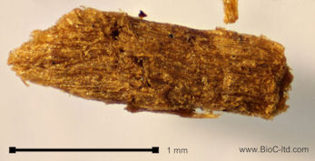
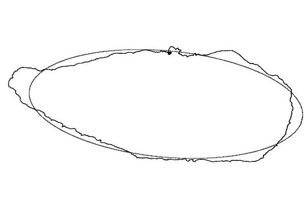
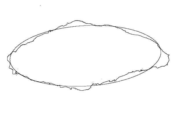
Using image processing it is possible to identify the outline of an individual particle and then measure its area and the length of the perimeter. The computer can also fit an ellipse, with the same area, to the shape of the particle. The major and minor axis is used to calculate the aspect ratio of the ellipse. This ellipse is essential to be able to calculate some shape factors used in commercial CFD packages for simulation of the fuel particle combustion. This method is demonstrated on a fuel particle below.
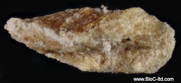
Image analysis software can be used to identify the outline of the particle and fit an ellipse with the same area to the shape of the particle.
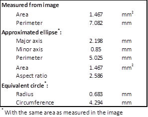
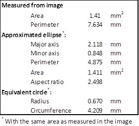
It is now possible
for the software to calculate the
projected area of the particle on the plane of the paper and the
perimeter of
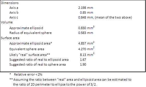
that projection. The table below shows the projected area and perimeter
of the particle together with length of the axes of the ellipse and its
perimeter, area and aspect ratio, finally the radius and circumference
of circle with the same projected area as the particle is given.
A second picture of the same particle but taken perpendicular to the first is analysed in the same way.
It is now possible
to use this information to define the
particle in three dimensions. It is here assumed that the ratio between
the “real” surface area of the particle and the surface area of the
best fit
ellipsoid is the same as the average of the ratio between the measured
particle
perimeter in 2 dimensions and the perimeter of the best fit ellipse
raised to the
power of 3/2 for the two analysed images. The ratio of real area to
area of the
equivalent sphere is calculated from the area of a sphere with the same
volume as the approximated ellipsoid. This method can be extended to
use 3 pictures taken from perpendicular directions, which would give
even more accurate results.